“http://www.cisco.com/en/US/docs/voice_ip_comm/cucme/admin/configuration/guide/cmemoh.html#wp1010511
According to Cisco all that is required is a cable to connect to your live feed device, a fxo or e&m port, a dial-peer and an ephone-dn.
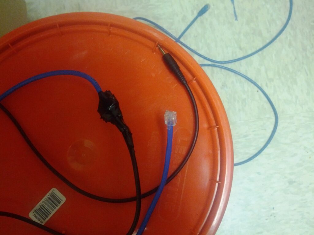
The cable we made on our own out of a bit of cat5, a RJ11 head and male to mail 3.5mm audio cable.
For those interested, the 3.5mm cable was the type with one wire running through the middle and another wrapped around like a sheath. The blue pair of the cat5 was then connected to the two lines from the audio cable using a couple of butt splices. These were then wrapped individually with electrical tape to prevent interference and then all wrapped together to make the finished product a little less rough (pictured below). A RJ11 head was then connected to the other end of the cat5 using the blue pair in the middle two pins.
I initially thought the issue might be with my homemade cable as it does look a little kludgy but I wanted to continue researching to eliminate all configuration issue.
Again, another user saved the day by providing portions of a working config for me to compare my config against. After making the changes suggested in the online article, the live feed from an iPod worked without issue.
First up, the initial config that should have been working per the above cisco article.
This is an FXO card.
!
voice-port 0/1/0
signal loopStart live-feed
input gain 0
description To MoH Live Feed
!
!
dial-peer voice 888 pots
destination-pattern 888
port 0/1/0
!
!
telephony-service
.
.
moh music-on-hold.au
.
.
!
!
ephone-dn 88
number 4
moh out-call 888
As you can see it consists of a voice port, with the command signal loopStart live-feed (this is essential if you’re using your own cable as Cisco states that without this command you will need an external battery to provide analog power to the jack) and a gain of 0, a dial-peer with a destination pattern of 888 and an ephone-dn with a number of 4 and a moh out-call number of 888 to match the dial-peer.
Now for the revised and working config
voice-port 0/1/0
signal loopStart live-feed
input gain 0
description To MoH Live Feed
!
!
dial-peer voice 888 pots
destination-pattern 888
port 0/1/0
!
!
telephony-service
.
.
moh music-on-hold.au
multicast moh 239.1.1.1 port 2000
.
.
!
!
ephone-dn 88
number 4
moh ip 239.1.1.1 port 2000 out-call 888
As you can see, just adding two lines fixed my configuration. Both of these items are listed in the Cisco configuration document but are listed as optional. If you are wondering, the multicast IP is not something you have to set or define anywhere other than here, you just pick one in the multicast range.
So in summation, if at first your config doesn’t succeed, be sure to check for help online as sometimes the Cisco docs just don’t cut it!

